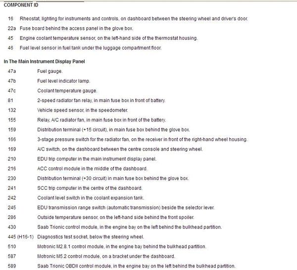
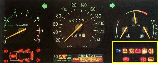
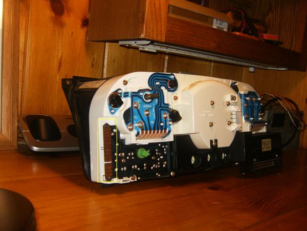
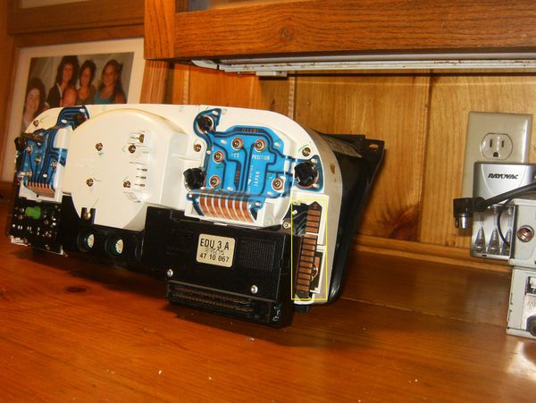
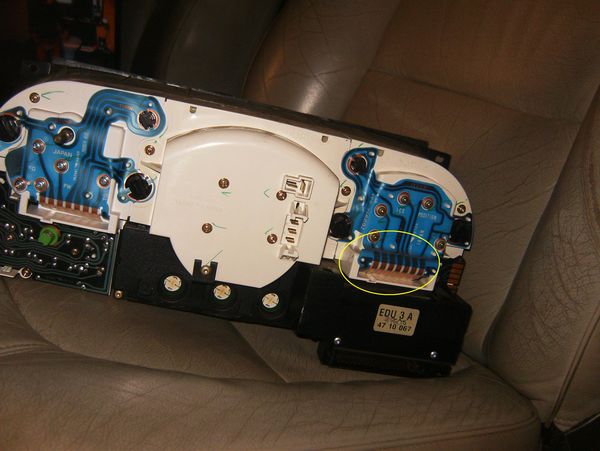
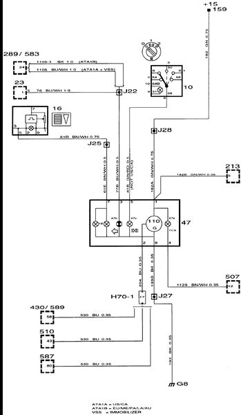
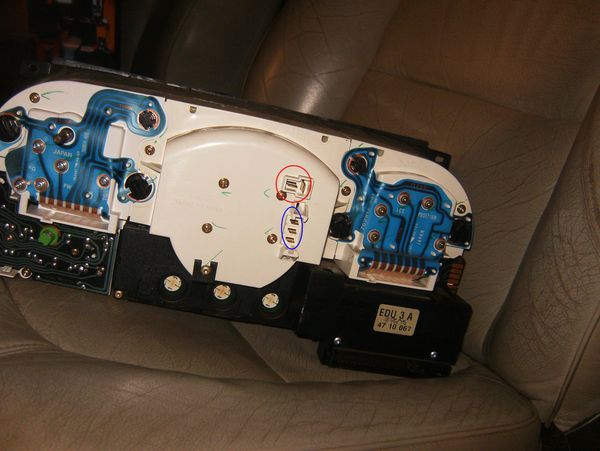
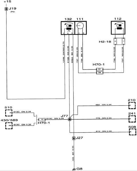
Schematic and brief explanation of the "Combined Instrument" (i.e. the fuel tank & coolant temperature gauges):

The combined instrument (fuel gauge/engine temperature gauge) are both two pole instruments where one coil in each instrument is fed with about 12 V from control module pin 22. Both gauges are grounded to grounding point G8.
Fuel level gauge
The control module feeds 1 - 9 V on pin 24 to the second coil in the fuel gauge and in this way controls the gauge reading.
Engine temperature gauge
The control module feeds 1 - 9 V on pin 30 to the second coil in the engine temperature gauge and in this way controls the gauge reading.
The way I explain gas gauge operation on other (GM truck) forums - edited for a Saab 9000:
The fuel tank sender is connected to pins 33 & 26 of the EDU (via the WHT & BLK wires). A variable ohmic value - which is a function of tank level – is generated by a float that drives the sender’s integral wire wound resistor. The EDU receives the resistance value from the sender and then uses that input to generate a variable voltage (1-9 VDC) on pin 24 – that voltage is applied to the gas gauge at pin 1.
The variable voltage output from pin 24 of the EDU - when connected by the GRN wire to pin 1 of the printed circuit - forms the "sensing leg" of the gas gauge. Pin 1 on the printed circuit is connected to the positive side of the sensing leg’s coil. The negative side of the coil is connected to ground on pin 5.
The higher the voltage that the EDU applies to pin 1 ,the greater the electro-magnetic force created by the coil. Consequently the force that it (the measuring coil) exerts on the gauge's magnet increases. The magnet is attached to the lower end of the indicating needle.
In addition to the sensing leg, there is another - opposing - circuit called the "control leg". It is identical to the sensing leg in every way except that the positive side of its coil always receives a full 12 VDC signal from the EDU on pin 2 (as opposed to the variable voltage the sensing leg receives). The control leg’s coil is located on the opposite side of the magnet from the sensing leg’s coil. It's negative side is also grounded via pin 5.
So what you have is; two coils located on either side of an indicating needle - AKA the "ray". The ray is pivoted somewhere in the middle and has an integral magnet mounted at the bottom.
These coils create their own magnetic fields - the strength of which is a function of the electron flow (i.e. current) passing through them. When these circuits are energized - by turning the ignition switch to the RUN position - the opposing magnetic fields begin to "fight it out". Each coil tries to pull the magnet - mounted on the needle - towards itself.
Due to the fact that it always sees full battery voltage, the current flow through the control coil is essentially constant (as is it's magnetic force).
On the other hand, due to the variable voltage signal generated by the EDU (as a result of changes in the fuel tank level), the current flow/magnetic strength of the sensing coil can range higher or lower.
The location of the two coils - to the magnet - is such that:
1. The control leg is always trying to peg the indicating ray to the FULL end.
2. The sensing leg is always trying to peg the ray to the EMPTY end.


