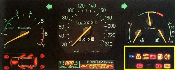
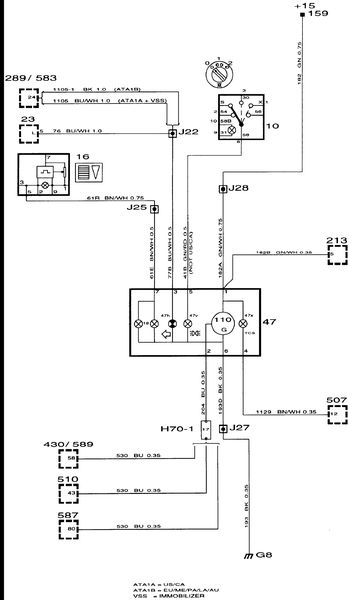
They fail to mention that after the ignition switch, the +15 is fed through fuse #13 - and then to the EDU and the warning lights section of the instrument panel. These warning lights:
Which are connected at this pin set:
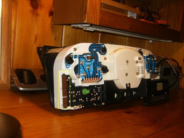
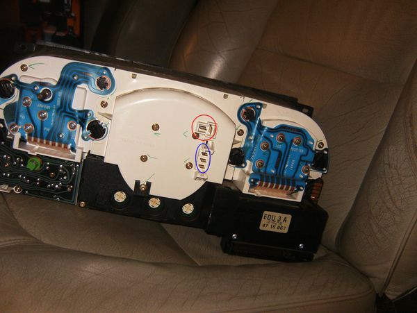
Just as useless info, the pictogram lights are supplied at this set:
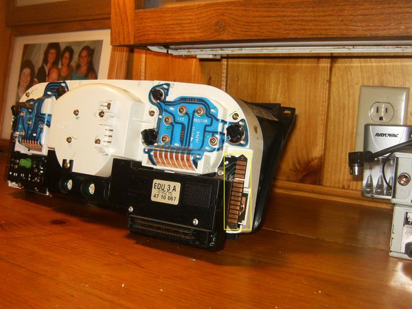
On the other side of the panel - above the pictogram - there is an additional printed circuit. It has 7 pin connections like the one on the other side. There is not much going on over there. Usually just the tach, LH directional indicator and the backlighting. There are provisions for a "lights on" indicating lamp (not used in the US or Canada) and a TCS lamp.
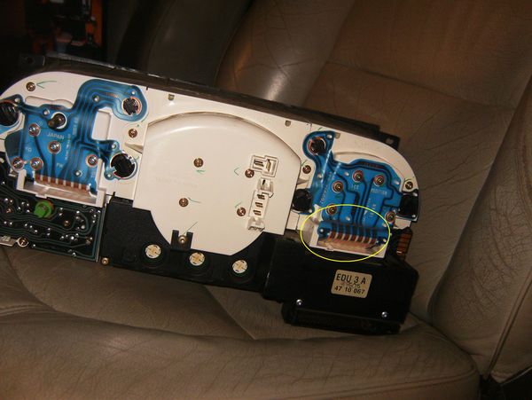
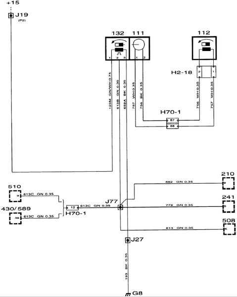
Might as well cover everything. Last are the 2 connections in back of the speedometer. There is a 2 pin and a 3 pin connector:
The 2 pin is in from the signal generator (mounted on the transmission) and the 3 pin is out from the vehicle speed sensor (which receives input from the speedometer itself). That speed sensor signal is used by a number of components:
 COMPONENT ID
111 Electronic speedometer in the main instrument display panel.
112 Sensor, electronic speedometer, on the gearbox.
132 Vehicle speed sensor, in the speedometer.
210 EDU trip computer in the main instrument display panel.
241 SCC trip computer in the center of the dashboard.
256 Speed warning buzzer, in the center console's bottom storage compartment.
356 Speed warning control module, at the rear of the bottom storage compartment in the center console.
430 Saab Trionic control module, in the engine bay at left on the bulkhead partition.
508 Cruise Control system control module, adjacent to the battery tray.
510 Motronic 2.8.1 control module, in engine bay behind the bulkhead partition.
589 Saab Trionic OBDII control module, in the engine bay at left on the bulkhead partition.hhhh