SaabCentral Forums banner

Fun Fan Project

1 reading
6.1K views 24 replies 5 participants last post by  jvanabra  
#1 ·
A few months ago I rehabbed my 2005 Jeep Liberty CRD, and part of that adventure was eliminating the crank-driven mechanical fan and replacing it with a gigantic 600w electric fan from a BMW. It was a fun adventure... I was out of touch on exactly how amazing modern radiator fans are!

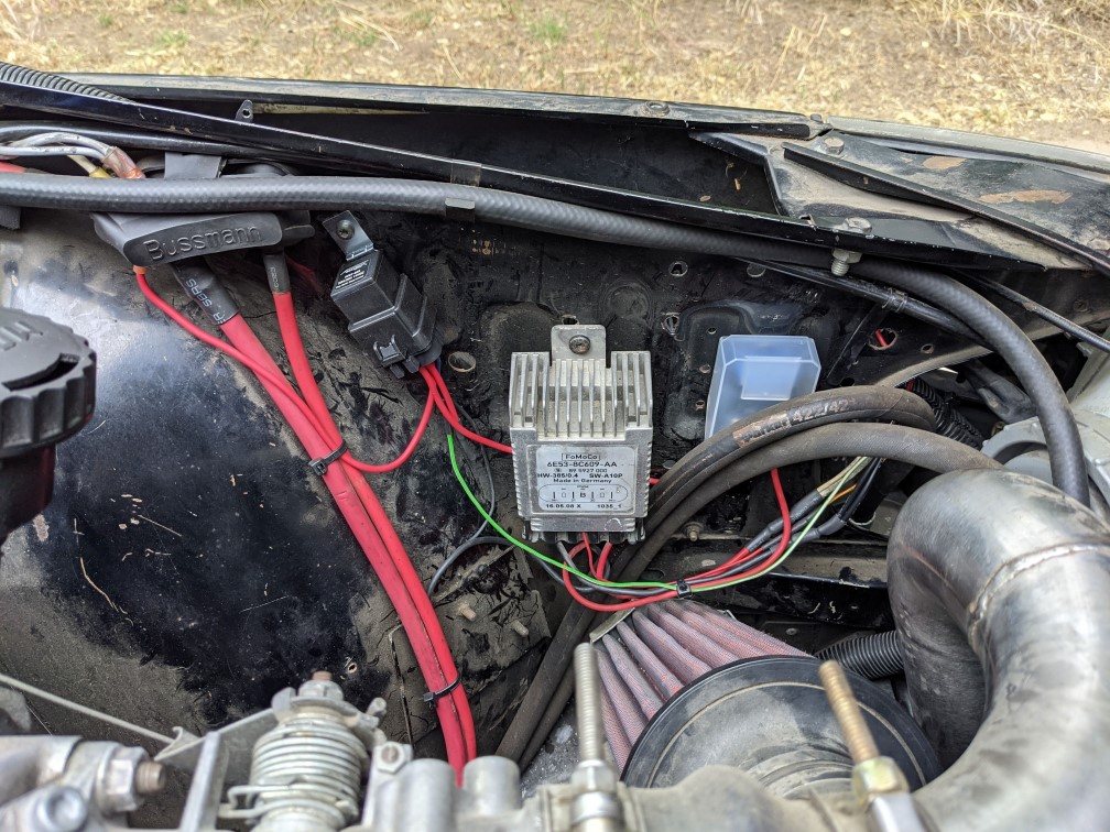
It's been a rip-roaring success, so I'm going to replicate pieces of that project on a c900. Here's most of the parts:
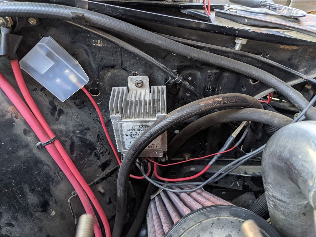
Image


The key bit in that photo is the silver Ford fan controller - part number 6E53-8C609-AA. It's found on later 1st gen Fusions. It's also GM part number 10377609 found on C6 Corvettes. It probably shows up other places, too.

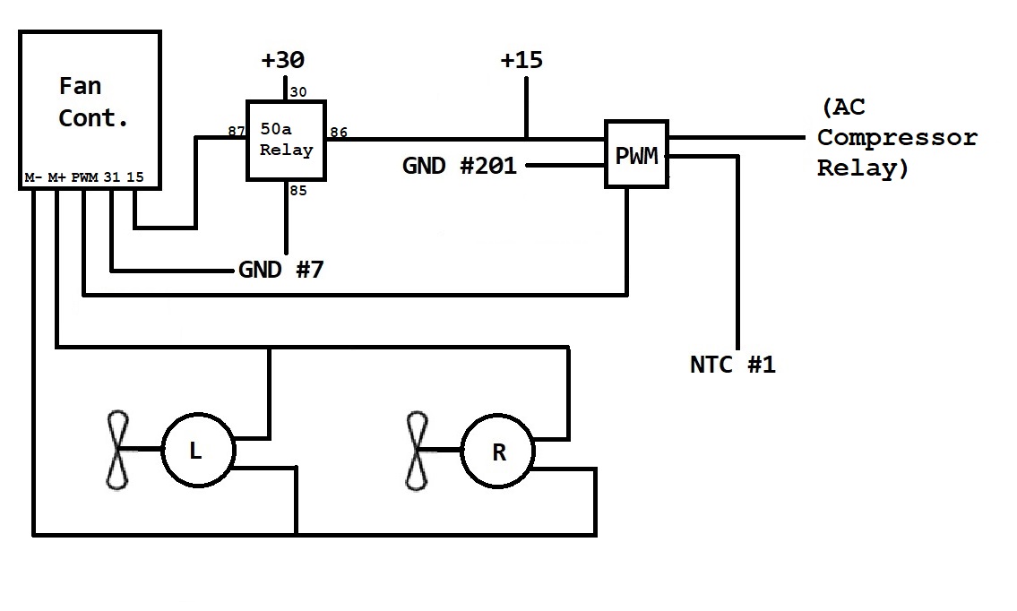
This magic box takes in battery voltage and a PWM signal, and then uses that to modulate power to a DC fan. In concept, it's like the 2-speed fan on the 9000/9-3/9-5 BUT rather than using a resistor to get two speeds it has an infinite number of speeds. (Probably, that's not true - it's probably stepped and just has "a lot" of speeds).

The benefit of using PWM is two-fold: We eliminate high inrush current associated with accelerating a fan from stopped to full speed, which on a c900 should reduce that annoying sag in idle speed when the fans kick in. Also, rather that wait until the engine is "too hot" and then race to cool it down, we can run a fan at low speed relatively early to take the edge off, and accelerate the fan as necessary. In theory, this should result in more stable engine temperatures and reduced load on the electrical system (maybe increase fuel economy a smidge).

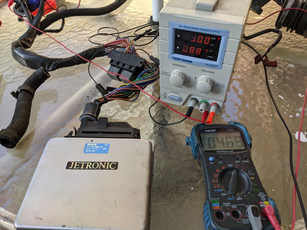
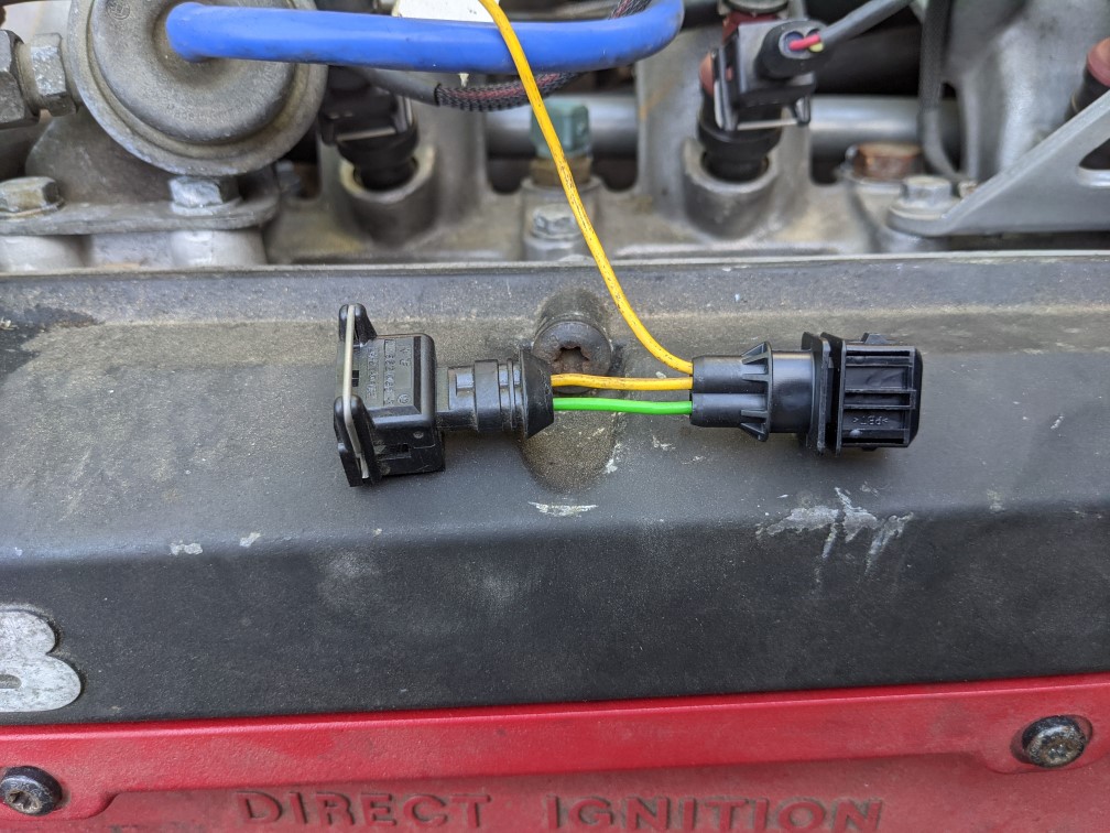
On modern-ish cars, the PWM signal is generated by the ECM in response to ECT. Well, a 900 can't do that. In my mock up, I've used a little PWM signal generator to prove the controller can drive the factory fan quietly. The controller is rated for 60a IIRC, so running both fans isn't an issue... I'm just running one here.

Here's how it looks:


(this video will self destruct in 30 days)

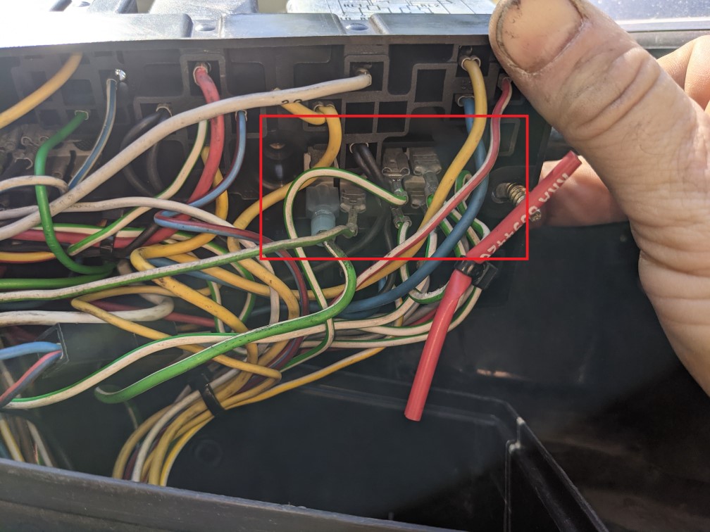
On the Jeep, I used this little doodad:


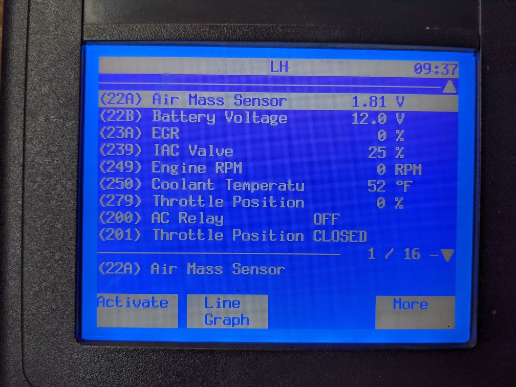
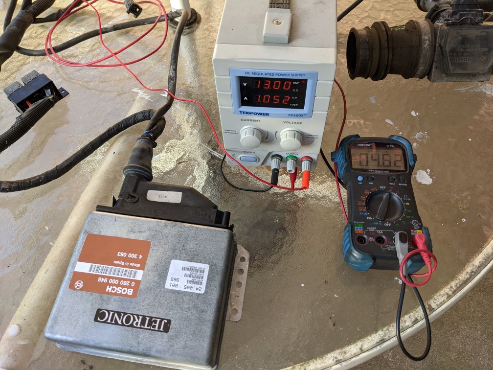
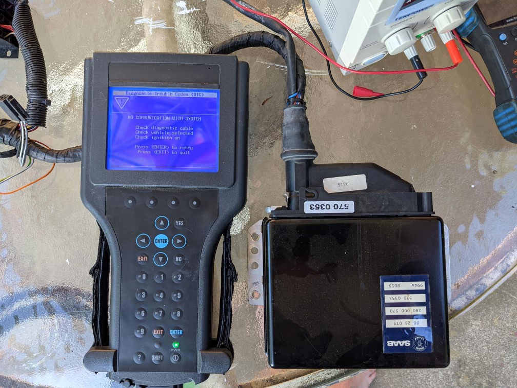
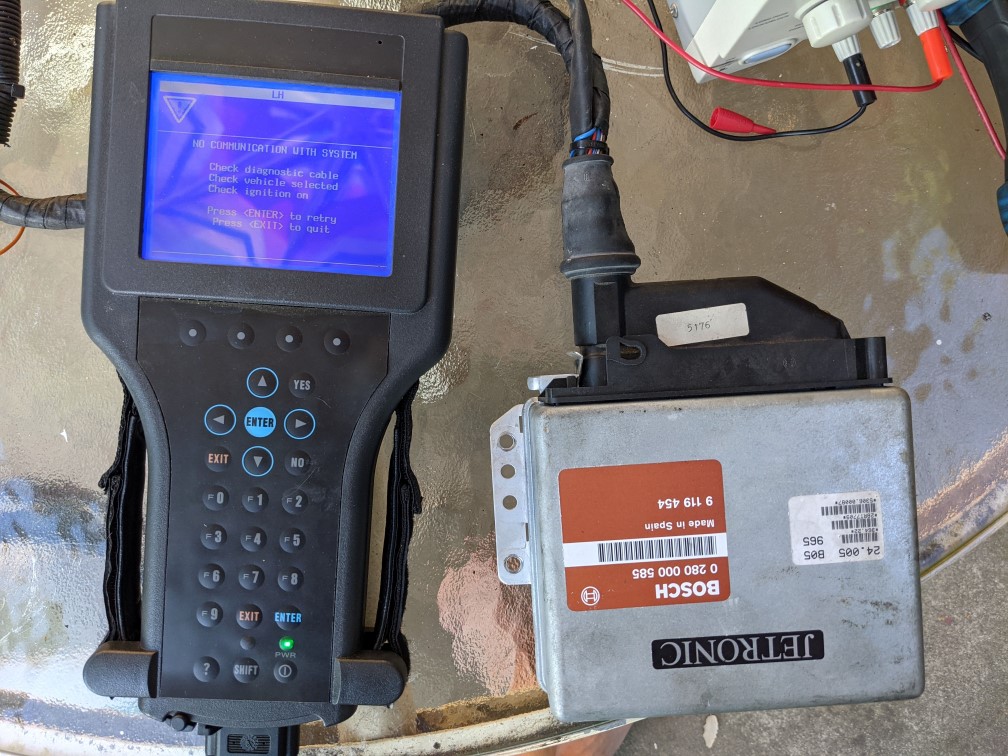
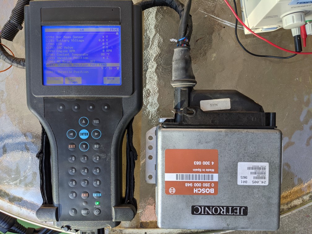
which works a treat. It pilfers the output from the factory ECT sensor and uses the actual engine temp to ramp the fan up as necessary. My plan is to use this device on the 900, too. The concern I have is that the min and max temperature the doodad needs must be separated by .8v (IIRC) and I think operating range of the c900's ECT sensor (like cold engine to very hot engine) is a fairly narrow range. Also, whereas on the Jeep I could use an OBDII scanner to monitor the ECT sensor and ensure my set points were good, that's not an option for the c900. I'm hoping - but don't remember - that Tech 2 can display ECT from LH 2.4.... The alternator is to use an external sensor, maybe also mounted in the intake manifold - but I'm hoping to avoid that.

Wish me luck!
 
#4 · (Edited)
Will do. i have the '93 running LH 2.4.2 which I know will report ECT:

Image


but I don't have anything running 2.4 right this second. I can probably fire up an ECM outside a car, though. It's not that many wires!

You could do this with 2.2 via trial and error, but 2.2 has no interest for me so... I don't care. :D

Anyway, IIRC:

The right fan is controlled by the time delay relay and the radiator fan switch OR the AC compressor relay. The relationship of switch to TD relay changes at some point - 1990? - but it doesn't matter.

The left fan is controlled by the AC compressor relay and AC radiator fan relay.

So here's how it'll get wired:

Image


The fan controller is designed for engine bay installation - the factory location is on the fan shroud so also very close to the exhaust. I think it should be safe just about anywhere in a c900's engine bay.

The temperature controller is safe for under hood installation, and can be weatherproofed. I'm very likely going to put mine inside the fuse panel... I'll just use molding tape to stick it where the old AC fan relay was. It does mean bringing the NTC & ground wire across the firewall, but it's a safe and convenient location.

One thing that might be missing here is that the fan will always turn off with the ignition. I kind of like giving the fan an opportunity to run after the car is shut down. Two options would be: 1) Power the temperature controller from #87 of the factory time delay relay (does anyone know what the "time delay" is?) OR 2) get an external time delay relay. Hella makes a $40 adjustable one that would slot in where the factory relay goes and work natively with '90+ cars and with some minor mods on earlier cars. Maybe Rev 2, if it becomes necessary.

I think the thing I need is a high-amp fuse holder for the fan controller - probably something like a 60a maxi fuse like I used on the Jeep

Image
 
#5 ·
Probably this info exists somewhere, but LH 2.x uses the same 5v reference for the ECT sensor as pretty much every EFI scheme they ever did. No surprise.

LH 2.2:

Image


LH 2.4

Image


This means that the magic doodad is capable of working with the factory sensor.... so next test is correlating temp with voltage to be sure there's a .8v spread.

Skipping ahead, I wanted to be sure I could set the magic doodad with reasonable accuracy, which means making sure I have a convenient way to read the temperature in real time. Out with a bunch of LH 2.4 ECMs.

What I learned is that early versions of LH 2.4 apparently don't talk to Tech 2!

570 ECM from '89 = FAIL

Image


585 ECM from '90 (IIRC) = FAIL

Image


948 ECM from '92 = SUCCESS!

Image


TBH, I think I knew this from a couple years ago. But now I have a record of it.

One thing I noticed during the experiment is the refresh rate of ECM data is really slow. On the Jeep I just used a heat gun to set the magic doodad, but that probably won't work here.

Anywho, some tidbits from the project.
 
#6 ·
I was thinking on this last night and had what might be a good thought...

The way you set the magic doodad is by pressing one button for minimum temp and another button for maximum temp, and then the magic doodad scales the fan speed between those two temps in several steps.... Since we know the characteristics of the factory sensor, all I need to do is simulate its output with resistors and use that to set the fan... eg, stick a 210ohm resistor where the sensor was to simulate ~90C, a 180ohm resistor to simulate ~95C, and a 160ohm to simulate 100C. Should be quite precise.

I guess I need to do some datalogging in the SPG and see what engine temps look like during normal operation. I've never really paid attention.
 
#8 ·
The tiny pin on the A/C relay gives the LH ECU 0.5 secods warning before applying the compressor load. In 9000s Auto- trans cars give a similar advance warning that transmission load is coming. LH blips the AIC valve a little so the engine doesn't bog.
You could probably hijack one of those signal inputs.
 
#9 ·
That would be a pretty solid idea... that would give the radiator fans a head start before the AC compressor kicks on.

It increasingly looks like it'll be another month before the '87 is back together, so I'll be setting this up on my T5 '85 first, and it's AC-less. It'll at least be a lot easier to mount the fan controller, having no APC box, no ICM, and no airbox. Plus, the positive distribution junction is right by the air filter. Heh.

I ordered in the magic doodad, so maybe next weekend I can knock this out.
 
#13 ·
Just as a data point the newer cars run fans:

Low speed - 100 +/- 2C
High speed - 113 +/- 2C

I suspect the B202 can take at least the temps of the B204/B205, but by the same token I'm betting LH injection is less graceful at handling higher temperatures than Trionic, especially when it comes to boosted motors. Probably high temps and boost = knock. Although, I suppose the head gasket could also be superior on the later cars... IDK.

Anywho, initially I think I am going to work with a 95C on and then whatever is .8v higher than that for max speed. My gut is that it'll be somewhere in the neighborhood of 100C.
 
#14 ·
Sounds like you have everything under control. For the record, the other day I was parking in my driveway and noticed the fan come on. I popped the hood to see which one was on, left or right. I wasn't quick enough before it turned off. I waited for it to come back on. Here's the punch line, they both came on at the same time! I'm sure that doesn't happen all the time, but when circumstances dictate that it does, that's probably when the engine takes a bigger dip in rpm than with just one fan and almost dies!

Sent from my SM-G965F using Tapatalk
 
#15 ·
There was a TSB to enable this, and it was recommended on 2.1l cars. IIRC, from the factory only one fan is engaged by temperature, but both fans with AC. The TSB changes the behavior so that the fans come on as a pair.

I'm definitely going to treat them as such - with the hope that having both fans at 50% mean never running them at 100%. :)
 
#17 ·
Got started on this.... I resolved to install The Stuff near the air filter. If I had the stock air box this likely wouldn't work, but I don't, so it will... :)

Image


I realized as I got going on this that I left out a key component... a relay for the fan controller. I I wire it directly to the battery, the fan would have the potential to literally run forever, so it's gotta be shut down with the key. One more thing I gotta bolt up... this weekend.

I intercepted the left and right fans in the wire harness that runs from the fusebox. Since this is a T5 car there is no ignition system or APC system running through this harness, making it easy to pull out individual wires. In another situation, I might be tempted to run new wires... but maybe not. Less wires and less confusion is always good. :)

Image


Under the fuse panel are a pair of junctions, one for switched power and the other for ground. I grabbed the former, and ran it down the aforementioned harness to the controller... that's how the relay will be engaged. At the same time, I also ran the PWM wire from the controller up the harness into the fuse panel.

Image


I had originally planned on getting the temperature signal from the ECT sensor differently, but decided to make a little "adapter" to split off the signal I need. The primarily motivator here was I wanted to keep the engine wiring harness discrete, so making a permanent connection to the Magic Doodad would be a problem. With the adapter I can still have separation of chassis and engine harnesses.... as Saab intended it. :)

Image


A 50a relay for the fan controller will be here tomorrow, and I should be able to finish this over the weekend. The remaining "challenge" is figuring out where to ground the controller's power. Originally, I wanted to do that at the radiator ground point, but running a big 12ga wire that far is kind of a PITA and I'm not so enthusiastic about it. I think I'm going to try and ground it to the frame or body right by the air filter and see how that goes. (There is normally a ground point on the body here... but that went away with APC/Hall-Effect)

Although what I'm doing here applies to c900s in general, I have it pretty easy due to the T5 conversion - more space, less wires, etc. I'll probably repeat this on the '87 SPG too... assuming of course it works as well as I think it will. :)
 
#19 ·
Here's some random photos of the finished product...

Image


Well, almost finished... I have a little wire management to do on the controller, but everything is where it's gonna go.

Nothing hanging out here - running T5 it's so clean over here!

Image


Magic doodad sits where the AC relay used to be. It's not what I would consider perfect, but it's functional and out of the way...

Image


My relay panel is looking pretty dejected though... so ronery in there.

I took it on a drive today just to see how it did sitting at stop lights. Ended up stuck on the freeway in traffic for 30 minutes. Ambient temps were mid '80s - not hot for this area - but the fans did exactly what they should do and did it silently. Temps never got above 201F, which is exactly where they were with the stock fan switch in similar temps. That should be about 50% speed. so there is plenty of headroom to handle warmer temps. Still something to keep an eye on as it warms up around here, but everything looks good so far.
 
#23 · (Edited)
I guess summer is here.... 107 on Monday and hovering around 100 ever since. As much as I hate this weather, it was nice timing to test this fan project....

Sitting in traffic in 100F weather, basically bumper to bumper for 30 minutes, the car stayed around 195F. When the road opened up a little and I could cruise at 30mph for a half mile I would see them drop down to 190F. When sitting still for an extended period of time, temps would hit about 201F.

It feels like running at very low speed the fans are more likely to approximately maintain temperature or reduce it slowly rather than shed heat rapidly, but I think that's an ok outcome. I would rather have engine temps hold steady (within safe ranges!) than constantly rising and falling as that's hard on the head gasket etc. Since I never saw the temp go over 201F, it seems that I'm getting the result I want - parked in 100F weather, the engine stays a consistent 195F-201F; once I'm moving I get back down towards 190F quickly.

Here's a short video:


Temps aside, my car doesn't stutter when the fans kick on and - at least at these temperatures - I never once even heard the fans. Hopefully, this reduced cycling and reduced overall speeds will also net longer fan life. I might also net a little improvement in fuel economy, since the fans running at low speed takes fewer amps.

As a recap, this is a 250k mile motor with a close to a 10 year old radiator and about 3,000 miles on the head/water pump/thermostat/coolant/ Not new, but new-ish.
 
#24 ·
I love this project. I have a 99 which suffers the fan kick so badly, and if the fuse dies then you have about 2 minutes to notice before the gauge is in the top red.

It looks like from the eBay website that the 99 could also be fitted as they sell the power supply to down rate 12V to 5V.

Could I use the NTC 99 thermistor without modification somehow? it doesn't work on voltage, per se, but impedance. also the NTC is non-linear I think but maybe that wouldn't matter.

They also sell an RTD thing I could screw in somewhere to get the temperature of the outside of the engine.

I'm still digesting everything but I'd love to step the DC fan instead of that massive kick and noise. and more importantly stop the temperature bouncing around 80-100 all the time.
 
#25 ·
The doodad only works on voltage, so I think you will need an auxiliary sensor. I would probably try and use a thread adapter ("bushing") to replace the fan switch in the radiator with their sensor or something along those lines. I think the 99 uses the same M22 thread as a 900, so you might have to tap a bolt.

On an h-motor you could use one of the spare holes in the intake manifold for an extra sensor, but I don't think those exist on a 99. Maybe an inline sensor adapter in the upper radiator hose?